Panasonic BY-HPE11KTA Installation Guide
Browse online or download Installation Guide for Camera accessories Panasonic BY-HPE11KTA. Panasonic BY-HPE11KTA Installation Guide User Manual
- Page / 36
- Table of contents
- BOOKMARKS
- BY-HPE11KTA 1
- Product Overview 2
- Main Features 3
- Other Information 4
- Network security 5
- 6 Installation Guide 6
- Included Items 7
- For Your Safety 8
- Installation Guide 9 9
- 10 Installation Guide 10
- Installation Guide 11 11
- Important Safety Instructions 12
- FCC Information 13
- General Precautions 14
- Precautions for Installation 15
- Caulk to waterproof 16
- 0.69 mm (0.027 inches) 17
- 1.37 mm (0.054 inches) 17
- Table of Contents 18
- 1 Main Unit 19
- Rear view 20
- Front view 21
- Camera adaptor 22
- Center adaptor 22
- 2 Mounting the Unit 23
- Screw (customer-provided 24
- Underside continuous 25
- Mounting bracket 26
- (M3x6: 6 pcs.) 26
- Installation Guide 27 27
- 3 Connecting the Unit 28
- Network camera 29
- LAN cable 29
- Network connector 29
- PoE switch 29
- 30 Installation Guide 30
- (length: 10 mm [3/8 inches] 31
- BNC connector cover 31
- SPEED button 33
- LAN COAXIAL 34
- Installation Guide 35 35
- Printed in Malaysia 36
- PNQX3079ZA KK1110MJ0 36
Summary of Contents
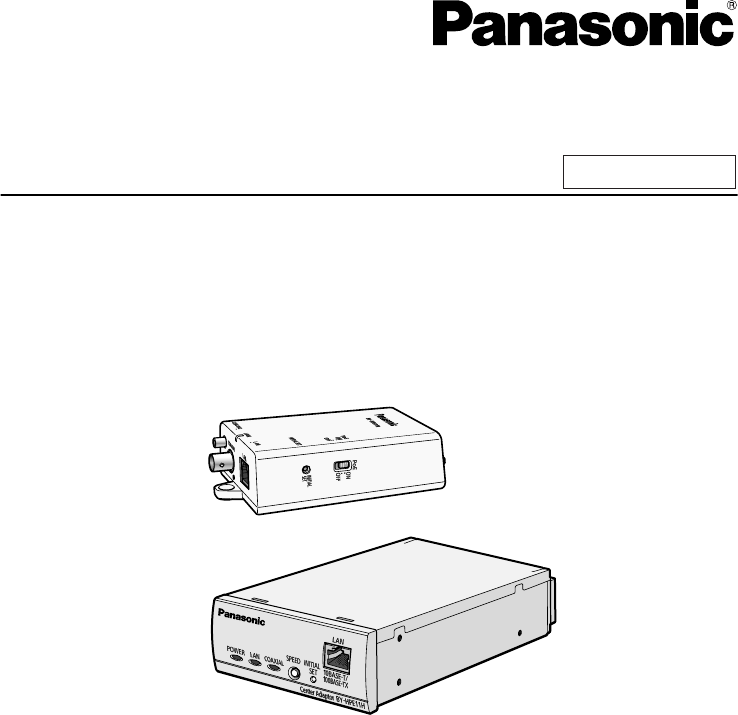
Installation GuideCoaxial - LAN Converter with PoE functionIndoor Use OnlyModel No. BY-HPE11KTABefore attempting to connect or operate this product
Turn the power off before performing wiring• This may result in electric shock, or result in fire from wiring shorts or incorrectwiring.Only use mount
Do not mount the unit to ceilings or walls made of soft materials• Do not mount the unit to soft ceilings or walls such as plasterboard, ALC (aeratedl
Important Safety InstructionsWhen using this unit, basic safety precautions should always be followed to reduce therisk of fire, electric shock, or pe
FCC InformationThis equipment has been tested and found to comply with the limits for a Class A digitaldevice, pursuant to part 15 of the FCC Rules. T
General PrecautionsFollow the instructions written in For Your Safety (see page 8) and Important SafetyInstructions (see page 12) together with the in
Precautions for InstallationAll electrical wiring should be performed by a qualified electrician.Consult an authorized dealer for installation.1. The
i.Mark points where you are going to make holes (2 places) according to theposition of the camera adaptor.ii.Mark a point where you are going to make
RG-6/U coaxial cableCoaxial CableTypeDC R/300 m (984feet 3 inches) ofInner ConductorMaximum CableLength (for PoEconnections)Maximum CableLength (forno
Table of Contents1 Main Unit ...191.1 Camera Adaptor (
1 Main Unit1.1 Camera Adaptor (BY-HPE11R)Front viewABCDEA IndicatorDisplays the status of the camera adaptor (seepage 22).B PoE switchTurns the PoE
Product OverviewThe BY-HPE11KTA is a coaxial - LAN converter capable of implementing long distance,high speed digital data transmission on existing co
Rear viewABCA Used when attaching the camera adaptor to aceiling or wall with screws (see page 24).B Used when attaching the safety wire (seepage 23).
1.2 Center Adaptor (BY-HPE11H)Front viewABCDA IndicatorsDisplays the status of the centeradaptor (see page 22).B SPEED buttonUsed when measuring the
1.3 Understanding the IndicatorsThe light indicators change depending on the operating status of the camera and centeradaptors.Camera adaptorIndicato
2 Mounting the Unit2.1 Mounting the Camera AdaptorPlease read the following information before mounting the camera adaptor.IMPORTANT• Mount the cam
2. Secure the camera adaptor to the wall or ceiling using screws (customer-provided,length: 20 mm [13/16 inches], body diameter: 4 mm [3/16 inches]).•
2.2 Mounting the Center Adaptor to a RackBy using the Rack Mount Connecting Fitting (sold separately), 3 or 4 connected centeradaptors can be mounted
• Connecting 4 center adaptors(Recommended torque 0.4-1.0 N·m {4.1-10.2 kgf·cm})Screw (Flat-head M3x6: 32 pcs.)Underside continuousconnecting bracket2
3. Secure the connected center adaptors to the rack.• Securely mount the center adaptors to the rack with the rack mounting screws(customer-provided,
3 Connecting the Unit3.1 Connection ExampleABCDEFFGNetwork cameraCamera adaptorCenter adaptorSwitching hub (or similar device)Network deviceLAN cab
• When connecting to network cameras not made by Panasonic, the PoE functionmay not be able to supply power using cross-pair LAN cables. Confirm thesp
Main FeaturesPoE (Power over Ethernet) readyThe coaxial - LAN converter is compliant with PoE standards (IEEE 802.3af), andcontains a power supplying
2. First pass the coaxial cable through the included BNC connector cover, then connectthe coaxial cable to the BNC connector of the camera adaptor.Coa
3. Secure the BNC connector cover with the included screw to the camera adaptor.(Recommended torque 0.4-0.8 N·m {4.1-8.2 kgf·cm})Screw(length: 10 mm [
5. Secure the BNC connector cover with the included screw to the center adaptor.(Recommended torque 0.4-0.8 N·m {4.1-8.2 kgf·cm})Screw(length: 10 mm [
8. Turn the power on for the network cameras and network devices, then check theindicators of the adaptors.GreenGreenGreenGreen9. Press the center ada
10. Confirm that all 3 of the center adaptor’s indicators are lit (for about 6 seconds).POWERLAN COAXIAL(Green)(Green)(Green)34 Installation Guide3 Co
Installation Guide 35Notes
www.panasonic.com/business/For customer support, call 1.800.528.6747Three Panasonic Way, Secaucus, New Jersey 07094 U.S.A.5770 Ambler Drive, Mississau
Other InformationAbout the user manuals• There are 2 sets of operating instructions for this unit as follows.– Installation Guide: Explains how to ins
2. PERSONAL INJURY OR ANY DAMAGE CAUSED BY INAPPROPRIATE USE ORNEGLIGENT OPERATION OF THE USER;3. UNAUTHORIZED DISASSEMBLE, REPAIR OR MODIFICATION OF
• For security, reset the unit when sending the unit for servicing, discarding the unit,or giving the unit to someone else (see 2 Resetting the Unit
Included ItemsConfirm that the following items are included in the unit’s packaging.• Installation Guide (this document) (1 pc.)• Warranty Card*1 (1 p
For Your SafetyTo prevent severe injury and loss of life/property, read this section carefully before usingthe unit to ensure proper and safe operatio
Do not touch the unit, LAN cable, coaxial cable, AC cord, or power plugduring thunderstorms• This may result in electric shock.Do not use the included
Related products and manuals for Camera accessories Panasonic BY-HPE11KTA
 (36 pages)
© 2020, manymanuals.com. All rights reserved. | 1.659 s |
 Manymanuals.com
 Manymanuals.de
 Manymanuals.fr
 Manymanuals.it
 Manymanuals.pl
 Manymanuals.cz
 Manymanuals.es
 Manymanuals-pt.com
Comments to this Manuals