Panasonic MC-E761 User Manual
Browse online or download User Manual for Vacuums Panasonic MC-E761. Panasonic MC-E761 User Manual
- Page / 18
- Table of contents
- BOOKMARKS
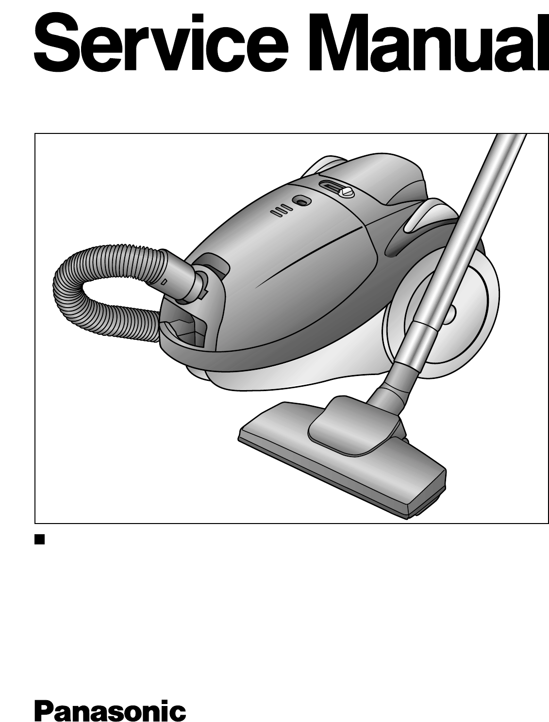
- MODEL MC-E761 1
- TABLE OF CONTENTS PAGE 2
- PICTORIALWIRING DIAGRAM 3
- SCHEMATIC DIAGRAM 3
- EXPLODED VIEW 4
- SPARE PARTS LIST 7
- • MOTOR / CARBON BRUSHES 9
- REPLACEMENT OF MAIN PARTS 10
- REMPLACEMENT OF MAIN PARTS 11
- • THERMAL CUT-OUT 12
- • CORD REEL UNIT / POWER CORD 14
- • BRAKE LEVER UNIT 16
- TROUBLE SHOOTING GUIDE 17
- PACKING INSTRUCTIONS 18
Summary of Contents
SPECIFICATIONSMC-E761Power source AC230VAC230-240V Depending on version50HzInput power (max.) 1500WVacuum 29 kPaPower cord length 5 mRadio of operatio
10REPLACEMENT OF MAIN PARTS3. Remove 7 screws from upper body and take out front coverand upper body. (Fig. 3)4. Remove black and white lead wires (pr
11REMPLACEMENT OF MAIN PARTS5. Disconnect yellow and black lead wires (provided withquick-connect terminal) from the power control circuit tabs.(Fig.
12REPLACEMENT OF MAIN PARTSFig. 11(2) Carbon brushes NOTE: The two carbon brushes should be replaced atthe same time.1. Take out motor unit and remove
13REPLACEMENT OF MAIN PARTS• POWER CONTROL CIRCUIT / ON/OFF SWITCH /SLIDING POTENTIOMETER(1) Power Control Circuit1. Take out cord reel ass’y and moto
14REPLACEMENT OF MAIN PARTSFig. 15(3) Sliding Potentiometer1. Remove upper body as explained previously in paragraph(1) “Motor”, points 1-3.2. Take ou
15REPLACEMENT OF MAIN PARTSFig. 183. Separate cord reel unit and cord reel support. (Fig. 18)4. Replace the cord reel unit with a new one. 5. Reassemb
16REPLACEMENT OF MAIN PARTSFig. 22Brake lever unitFig. 23• BRAKE LEVER UNIT1. Remove upper body as explained previously in paragraph(1) “Motor”, point
17TROUBLE SHOOTING GUIDECONDITION CHECKPOINT METHOD OF INSPECTION CAUSE / REMEDYMotor fails to rotate. Power cord Check power cord continuity between
18PACKING INSTRUCTIONSBedienungsankeitungGebruitesaannijeungInstructions d'utilisationBruksanvisningBruksanwisningBrugervejkedningVacuum CleanerM
2TABLE OF CONTENTS PAGESPECIFICATIONS ... 1SCHEMATIC DIAGRAM ...
3PICTORIALWIRING DIAGRAMMC-E761MOTORYellowBlackBlack BlackWhiteCORD REELTHERMALCUT-OUTPOTENTIOMETERON/OFFSWITCHPOWERCONTROLCIRCUITBlueGreySCHEMATIC DI
4EXPLODED VIEW151611123013143329323536312827291034
5EXPLODED VIEW584526252243241817411839384246443823241918505154535549484757372120405256
6EXPLODED VIEW96062656364616659Instrucciones de ManejoOperating instructionsManual de instruçoesMC-E780, MC-E781, MC-E783Matsushita Electric España,
7SPARE PARTS LISTREF. No. DESCRIPTION PART No. Pcs/SetMC-E761REMARKS 1 HOSE UNIT AMC8A92T1034 1 • ✓2 HOSE AMC8A01K0034 1 • ✓3 HOSE CONNECTING
8SPARE PARTS LISTREF. No. DESCRIPTION PART No. Pcs/SetMC-E761REMARKS 50 CORD REEL UNIT AMC8P97P6000 1 • Applied to East & West European count
9REPLACEMENT OF MAIN PARTSIMPORTANT: Before replacing any part always DISCONNECT THE CLEANER FROM THE ELECTRICITY SUPPLY.• MOTOR / CARBON BRUSHES(1)
Related products and manuals for Vacuums Panasonic MC-E761


 (48 pages)
(72 pages)
(44 pages)
(28 pages)
(44 pages)
(48 pages)
(48 pages)
(56 pages)
(48 pages)
(12 pages)
(40 pages)
(48 pages)
(52 pages)
(56 pages)
(48 pages)
(44 pages)
(48 pages)
(48 pages)
(48 pages)
(48 pages)
(72 pages)
(44 pages)
(28 pages)
(44 pages)
(48 pages)
(48 pages)
(56 pages)
(48 pages)
(12 pages)
(40 pages)
(48 pages)
(52 pages)
(56 pages)
(48 pages)
(44 pages)
(48 pages)
(48 pages)
© 2020, manymanuals.com. All rights reserved. | 3.621 s |
 Manymanuals.com
 Manymanuals.de
 Manymanuals.fr
 Manymanuals.it
 Manymanuals.pl
 Manymanuals.cz
 Manymanuals.es
 Manymanuals-pt.com
Comments to this Manuals